

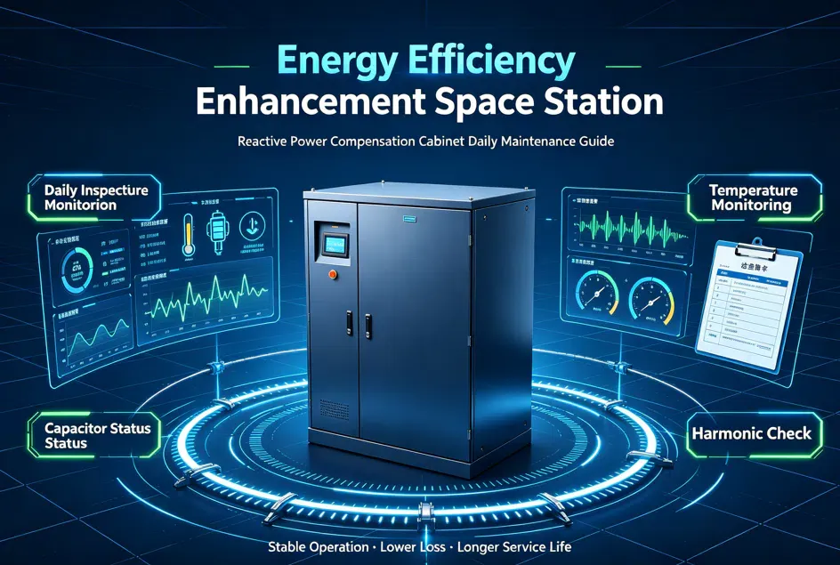
 The core of daily maintenance for reactive power compensation cabinets is to ensure that capacitors do not overheat, contactors do not weld shut, and the power factor meets the required standard. Daily inspections should focus on listening for sounds, observing status indicators, and measuring temperatures, with special attention to the cooling environment to prevent capacitor bulging and leaking, which can lead to explosion accidents.
Below are the key points of common knowledge for daily operation of reactive power compensation cabinets (capacitor cabinets):
1. Core Function and Operating Target
· Core Function: To improve the power factor by switching in capacitors to generate capacitive current, which offsets the inductive load (such as motors and transformers) in the power grid.
· Operating Target: To control the power factor within the range of 0.90 – 0.95 (typically the set value). A power factor below 0.90 may result in penalties from the power supply authority, while a value above 0.98 may cause over-compensation, leading to voltage rise and equipment damage.
2. Daily Inspection "Three-Step Method"
· Step 1: Check the Indicators
o Controller Display: Observe whether the power factor displayed on the controller is within the target range (e.g., around 0.92).
o Switching Status: Check whether the switching indicators for each circuit are flashing or steadily lit as normal. If all indicators are off, it may indicate a controller fault or that no current signal is being detected.
· Step 2: Listen to the Sounds
o Contactor Closing Sound: Under normal conditions, the contactor should produce a crisp "click" sound when closing.
o Abnormal Noise: If you hear a continuous "buzzing" sound or a harsh high-frequency noise, it is usually a discharge sound caused by a damaged thyristor module or an inter-turn short circuit in the capacitor. Immediate investigation is required.
· Step 3: Check Appearance and Instruments
o Ammeter Readings: The readings on the three-phase ammeters should be balanced and stable. If the current on one phase suddenly drops to zero or spikes sharply, it indicates a problem in that circuit.
o Capacitor Appearance: Check whether the capacitors show signs of bulging (swelling), oil leakage, or deformation. Bulging is a typical characteristic of gas generation from internal dielectric decomposition in capacitors and is a serious hidden hazard.
3. Key Maintenance Indicators
· Temperature Control: The operating environment temperature for capacitors should not exceed 40°C. During high-temperature summer periods, be sure to check whether the exhaust fans are operating properly and whether the filters are clogged. High temperature is a primary cause of shortened capacitor life.
· Power Factor Setting:
o Lagging: Current lags voltage, indicating an inductive load; capacitors need to be switched in.
o Leading: Current leads voltage, indicating a capacitive load (over-compensation); capacitors need to be switched out.
· Harmonic Monitoring: If there are a large number of variable frequency drives and rectifiers in the grid, reactors must be installed. Otherwise, harmonics can cause severe capacitor heating or even resonant explosions.
4. Common Faults and Handling
· Frequent Switching: Manifests as contactors repeatedly closing and opening. This is usually caused by an overly narrow power factor setting range or excessive load fluctuations. Adjust the controller's sensitivity or time delay settings.
· Fuse Blown: A blown fuse inside the cabinet is usually caused by an internal capacitor short circuit or breakdown due to excessive inrush current during closing.
· Controller Black Screen: Check whether the auxiliary power supply circuit is normal, or whether the controller itself is damaged.