

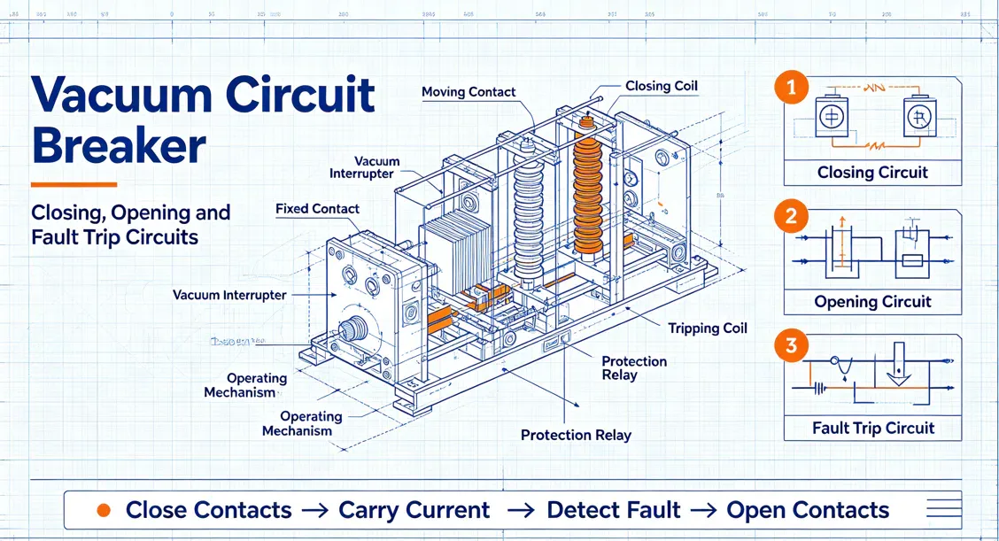
Vacuum Circuit Breakers: Closing, Opening, and Trip Circuits
In medium-voltage (MV) switchgear — spanning 3.3 kV to 38 kV — the vacuum circuit breaker (VCB) has become the global standard for protection and control. Its superiority in interrupting fault currents, near-zero maintenance, and environmental safety (no SF₆ gas) makes it the preferred choice for utilities, industrial plants, and EPC contractors worldwide. However, for international B2B buyers evaluating VCB tenders, the technical conversation must go beyond the interrupter bottle. The closing circuit, opening circuit, and trip (accident trip) circuit — collectively the breaker's secondary wiring — determine whether the device will operate reliably under fault conditions. Misunderstanding these circuits leads to incorrect specifications, nuisance tripping, and rejected FATs. This article provides a structured walkthrough of the three core circuits to help buyers ask the right questions and specify with confidence.
1. Overview: Why the Secondary Circuits Matter
A VCB is a mechanical device driven by an energy storage mechanism (spring, motor-spring, or magnetic actuator). The primary contacts operate inside a vacuum interrupter. But the decision to close or open — and the speed at which it happens — is governed by the control circuit. For buyers, the control circuit is where supplier quality differentiates itself: wiring discipline, relay selection, anti-pumping logic, and compliance with IEC 62271-1 / IEC 62271-100 determine field reliability. When you procure a VCB, you are not just buying an interrupter; you are buying a complete control system.
2. The Closing Circuit
The closing circuit delivers energy to the closing coil (also called closing solenoid or closing magnet), which releases the stored energy in the spring mechanism to drive the contacts closed. Key elements include:
- Closing coil (Y4): A short-time rated DC or AC solenoid. Typical ratings: DC 48 V, 110 V, 220 V; AC 110 V, 220 V. The coil must be energized only momentarily — continuous energization will burn it out.
- Closing spring motor: Charges the closing spring. The spring must be fully charged before a close command is accepted. A spring-charged limit switch (S1) blocks the closing circuit if the spring is not ready.
- Anti-pumping relay (K3 or 52Y): Prevents multiple close commands from being executed if the operator holds the close button depressed while the breaker is already closed. This is a critical safety feature — without it, the breaker could re-close into a persistent fault, causing catastrophic damage.
- Close push-button / remote close contact: Local or SCADA-initiated command. In modern panels, this is often a dry contact interfaced to a PLC or protection relay.
- Auxiliary contacts (52a / 52b): 52a contacts are closed when the breaker is closed; 52b contacts are closed when the breaker is open. These provide position feedback and interlock logic.
Buyer specification tip: Always require a closing time ≤ 100 ms and a close-spring charging time≤ 15 seconds (per IEC 62271-100). Verify that the anti-pumping function is hardwired, not software-dependent, for higher reliability.
3. The Opening Circuit
The opening circuit energizes the trip coil (Y3) to release the latch and allow the opening springs to separate the contacts. Key elements:
- Trip coil (Y3): Similar voltage ratings to the closing coil. Also short-time rated.
- Trip push-button / protection relay output: Local manual trip or automatic trip from a relay (overcurrent, earth fault, differential, etc.).
- Auxiliary contact interlock: Prevents opening if the breaker is already open (though most designs tolerate a trip signal in open state without damage).
- Shunt release / undervoltage release (optional): Some VCBs include a shunt trip coil for remote tripping or an undervoltage release that trips the breaker if control voltage drops below a threshold.
Buyer specification tip: Require an opening time ≤ 50 ms (typical: 20–45 ms). Confirm that the trip coil circuit is supervised — i.e., a small monitoring current detects open-circuit or short-circuit conditions in the wiring, alerting maintenance before a real fault occurs.
4. The Accident Trip Circuit
The accident trip circuit — sometimes called the protective trip circuit or emergency trip circuit — is the path through which protection relays command the breaker to open upon detecting a fault. This is the most critical circuit for system safety. It typically includes:
- Protection relay output contacts: Hard-wired to the trip coil circuit. Common schemes use a seal-in circuit(self-holding) so that the trip command persists until the breaker auxiliary contact confirms the breaker has opened.
- Master trip relay (86): In some designs, a master trip relay is interposed between the protection relay and the trip coil. It provides additional isolation and a visible flag to indicate a protective trip has occurred.
- Trip circuit supervision relay (TCS): Continuously monitors the integrity of the trip circuit wiring and coil. If a break occurs, an alarm is raised. This is essential for high-availability systems.
- Accident trip indication: A dedicated LED or flag on the panel that illuminates only on protective trip (not on manual open). This helps operators distinguish between a routine switch-off and a fault clearance.
Key distinction: In Chinese utility practice, the "Emergency trip " (accident trip) is specifically differentiated from a manual open. The accident trip circuit often includes a self-holding contact(e.g., 52b auxiliary) that keeps the trip coil energized until the breaker fully opens, preventing "incomplete tripping" if the relay output is too brief. For international buyers, ensure the supplier's schematic includes this feature if your grid code requires it.
5. Integration with Protection Relays and SCADA
Modern VCBs are rarely standalone; they are integrated with numerical protection relays (e.g., overcurrent, earth fault, distance). The control circuit must support:
- Hard-wired interlocks: Between disconnectors, earthing switches, and the breaker (e.g., 52b interlock to prevent closing with earthing switch closed).
- Communication: IEC 60870-5-104, Modbus, or IEC 61850 GOOSE messaging for status feedback and remote control.
- Testing provisions: A secondary injection test block (e.g., SFTB type) allows the protection relay to be tested without disconnecting the trip circuit wiring — a major time-saver during maintenance.
Buyer specification tip: Insist on a wiring diagram review as part of the FAT. Verify that all relay coils, contacts, and interlocks are clearly labeled per IEC 61346 or equivalent. A neat, labeled panel is a sign of a quality manufacturer.
6. Common Pitfalls and How to Avoid Them
- Undersized control cables: Voltage drop in long control cables can prevent the closing coil from picking up. Specify minimum cable cross-section (typically 2.5 mm²) and calculate voltage drop at the coil terminals.
- Missing trip circuit supervision: Without TCS, a broken trip wire may go undetected until a fault occurs — with catastrophic consequences. Make TCS a mandatory requirement for critical breakers.
- Incompatible voltage ratings: Mixing DC and AC coils in the same panel without proper isolation can cause nuisance operation. Standardize on DC 110 V or 220 V for consistency.
- No anti-pumping: As noted, this is a safety essential. Verify it is present and tested during FAT.
7. Standards and Compliance
The following standards should be referenced in your procurement specification:
- IEC 62271-100: High-voltage alternating current circuit breakers (includes VCBs up to 38 kV).
- IEC 62271-1: Common specifications for high-voltage switchgear and controlgear.
- IEC 60255: Measuring relays and protection equipment (for relay integration).
- IEEE C37.04 / C37.09: US standards for AC high-voltage circuit breakers (if targeting North/South America).
Conclusion
The vacuum circuit breaker is only as good as its control circuits. For B2B buyers, understanding the closing, opening, and accident trip circuits is not just an engineering exercise — it is a procurement safeguard. By specifying the right coil ratings, demanding anti-pumping and trip supervision, and verifying wiring discipline during factory acceptance, you ensure that the VCB will perform when it matters most: clearing a fault and protecting your network. Equip yourself with this knowledge, and you will evaluate VCB tenders with the confidence of a seasoned utility engineer.