
Product Overview
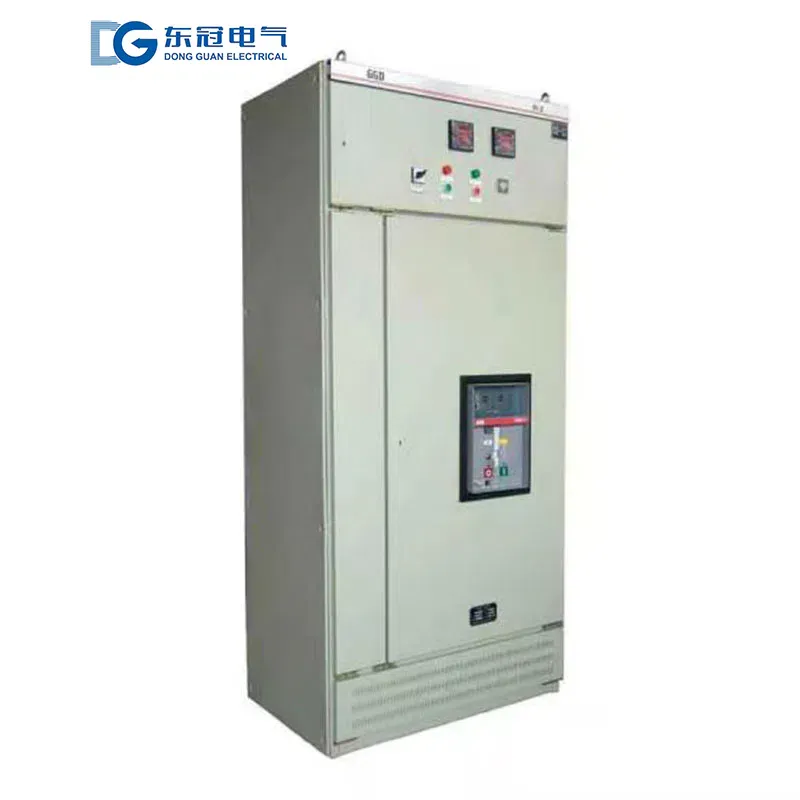
GGD series fixed switchgear is an indoor low-voltage complete distribution device, suitable for three-phase AC 50Hz, rated working voltage of 380V/400V single busbar and single busbar sectionalizing power systems. It is widely used in various low-voltage distribution scenarios such as power plants, substations, industrial and mining enterprises, high-rise buildings, municipal engineering, petrochemical industry, metallurgy, and textiles. It is mainly used for receiving, distributing, controlling, protecting, and monitoring electrical energy, and can adapt to power distribution, lighting distribution, motor control, reactive power compensation, and other working conditions. It is one of the representative products of assembled fixed-panel switchgear in China and can serve as a replacement for low-voltage complete switchgear.
The product adopts a fixed structure design, with key components made of high-quality materials. It features high breaking capacity, good dynamic and thermal stability, flexible electrical solutions, convenient assembly, high cost-effectiveness, reliable operation, and easy maintenance. It breaks through the structural form of traditional products, complies with national and industry standards such as GB 7251.1 and IEC 60439-1, and has passed CCC compulsory certification and ISO quality system certification. Its stable performance makes it one of the most widely used devices in the low-voltage distribution field.
Operating Environment
1. Ambient temperature: -5℃ to +40℃, 24h average temperature ≤ +35℃.
2. Indoor installation, altitude ≤ 2000m (customizable up to 3000m for special conditions).
3. Relative humidity: ≤50% at +40℃; up to 90% at +25℃. Condensation due to temperature changes should be considered, and anti-condensation devices should be installed if necessary.
4. Pollution degree: Level 3; customizable to Level 4 anti-corrosion protection.
5. Installation inclination: ≤5° from vertical.
6. Installation site: No fire, explosion, severe vibration, shock, corrosive gases, dust, or conductive dust. Keep away from strong electromagnetic interference. During transport and storage, temperature can range from -50℃ to +50℃, with short-term exposure up to +70℃.
Technical Parameters
| Parameter | Unit | Value |
| Rated working voltage | V | AC 380/400 |
| Rated insulation voltage | V | 660 (1000) |
| Rated frequency | Hz | 50 |
| Main busbar rated current | A | 630/1250/1600/2000/2500/3150 |
| Vertical busbar rated current | A | ≤800 |
| Rated short-time withstand current (1s) | kA | 16/20/30/50 |
| Rated peak withstand current | kA | 40/50/63/105 |
| Dielectric strength | V/1min | 2500 |
| Protection level | --- | IP30/IP40 (customizable from IP20 to IP40) |
| Dimensions (W×D×H) | mm | 600/800/1000×800/1000×2200/2400 |
| Unit circuit rated current | A | 10–630 |
| Applicable standards | --- | GB 7251.1, IEC 60439-1 |
Product Features
1. Fixed structure, stable and reliable – Fixed installation design, components fixed inside the cabinet with compact structure and standardized wiring, low contact resistance, high operational stability, and low failure rate. Suitable for ordinary distribution scenarios that require high power supply stability and accept short maintenance power outages. Effectively realizes energy conversion, distribution, and control functions.
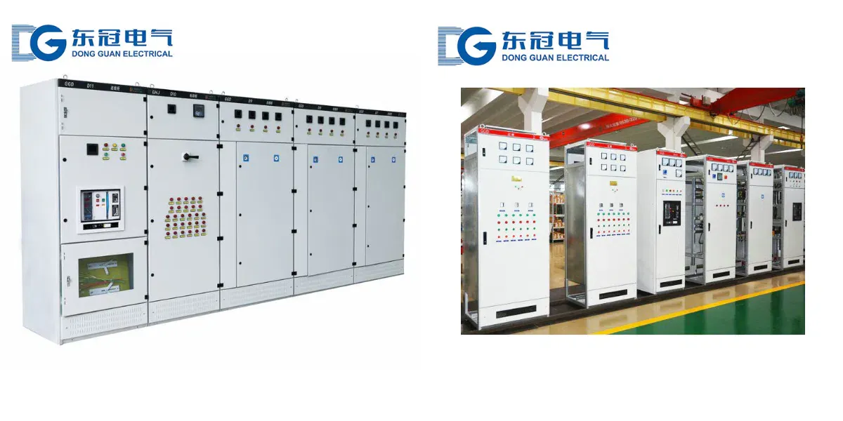
2. Flexible combination, strong versatility – Adopts a combined assembly structure. The frame is partially welded and assembled with 8MF cold-formed steel sections. All structural parts of the basic frame are fastened with screws, offering high general applicability. Flexible combination of incoming, outgoing, bus tie, and capacitor compensation solutions. Wide selection of main components, interchangeable between domestic and imported brands.
3. Excellent dynamic/thermal stability, high breaking capacity – Optimized busbar layout and structural strength, low temperature rise, strong short-circuit resistance, excellent breaking performance. Suitable for high-current continuous operation, effectively withstands short-circuit current impacts, ensuring safe operation of the distribution system.
4. Good heat dissipation, easy maintenance – Cooling slots at top and bottom create natural ventilation. Easy to install and remove cabinet doors (full door or double door structure). Complete grounding protection between door and frame. Simple daily inspection and maintenance, low lifecycle cost.
5. Flexible incoming/outgoing wiring, wide adaptability – Supports top, bottom, and side wiring methods. Reserved fixed positions inside the cabinet for installing relay protection and automatic devices for special users such as power plants. Strong installation flexibility without interference from component type changes or updates.
6. Corrosion-resistant and durable, high cost-performance – Cabinet made of high-quality cold-rolled steel, phosphated and electrostatic spray-coated (frame and doors coated with polyester textured baking paint after phosphating; all unpainted parts galvanized and passivated). High strength, oxidation resistance, corrosion resistance, anti-aging, attractive appearance, long service life, reasonable production cost, outstanding cost-performance ratio.
Our Advantages
1. Fast quotation response, professional primary/secondary electrical design, system optimization, and technical consulting tailored to GGD fixed distribution scenarios.
2. Standardized production lines, short delivery times, support for urgent orders, customization for special protection levels, wiring methods, and dimensions.
3. Comprehensive after-sales service including installation guidance, commissioning, training, and lifetime maintenance. Full support during operation, with specialized guidance for GGD series products.
4. Full certifications including CCC, ISO, type test reports, ensuring quality and compliance with national and industry standards.
5. Strict quality management from raw material procurement to finished product testing, with special focus on cabinet welding and component installation.
Ordering Guidelines
Please provide the following when ordering:
1. Main circuit scheme, secondary circuit system diagram, and auxiliary circuit control method, specifying whether relay protection and automatic devices are required.
2. Equipment layout drawing and distribution room layout for installation optimization.
3. Incoming/outgoing wiring method (top/bottom/side), busbar connection requirements, installation spacing, and fixing method.
4. Type, rated current, and short-circuit breaking current of key components (circuit breakers, contactors, etc.).
5. Any special environmental requirements (high altitude, corrosion protection, explosion protection, high protection level) or special functions must be specified in advance.